RXLP-1 Active Broadband Receive Loop
RXLP-1 Active Broadband Receiving Loop
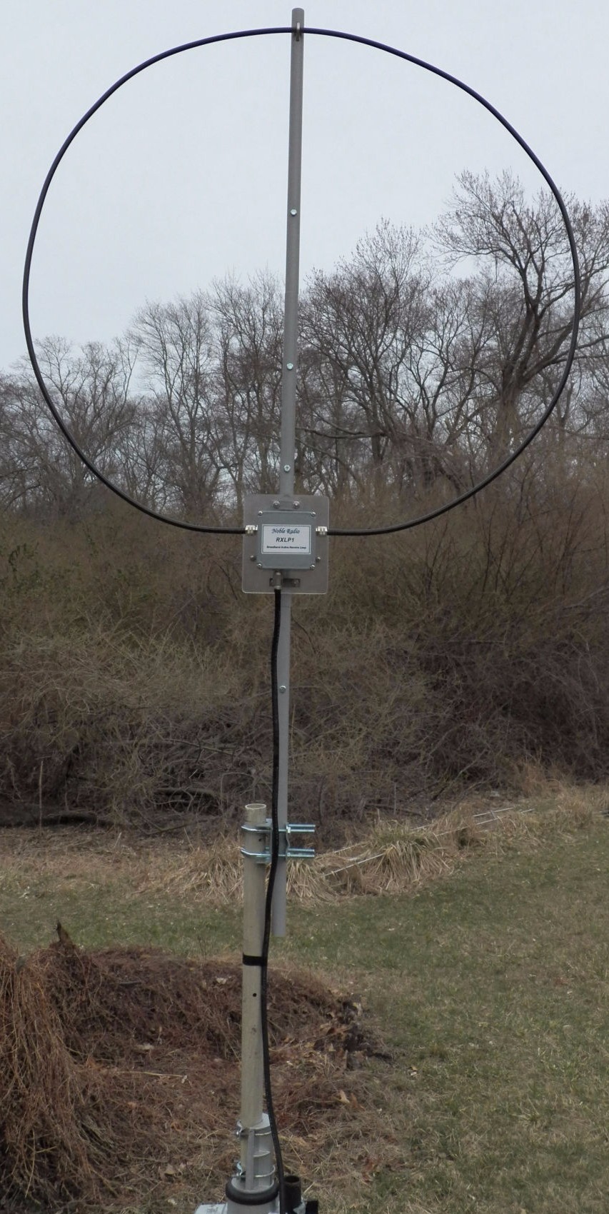
The Noble Radio RXLP-1 is a broadband receiving loop capable of operation from 300 Khz to 30 MHz using a broadband LNA (Low Noise Amplifier) and has a performance that is comparable to full sized dipoles over its range. The 39 inch diameter loop can provide a lower noise floor than a conventional dipole or vertical plus allows local noise sources to be minimized or eliminated by rotating the antenna. This null in the antenna pattern also allows interfering stations to be reduced or practically eliminated by rotation of the antenna.
The Mast section of the antenna is built from 1 inch OD fiberglass tube sections that connect together by inserting ¾ inch fiberglass tubing sections between them and bolting these together with stainless steel hardware. This makes for a very sturdy and resilient mast that is 69 inches long but breaks down to 23 inches for storage or portable operation. The loop itself is made from a 10 ft length of LMR-400 coax with PL-259 connectors on each end that screw into the SO-239 connectors on the sides of the LNA enclosure. These connectors provide a very sturdy and reliable connection to the loop. A mounting bracket is also supplied that allows the loop mast to be attached to up to a 2 inch OD pipe or fiberglass tube which is compatible with common TV type rotor installations. To obtain the best performance from the antenna it is recommended that it be used with a rotor. This will allow peaking (or nulling) signals and reducing or eliminating noise sources.
Click here to check the reviews on eHam.net
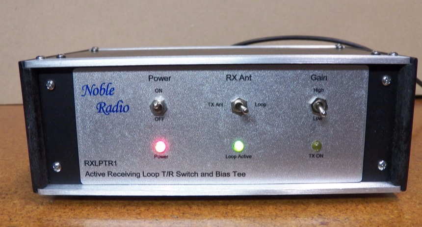
RXLPTR1 - Active Receiving Loop T/R Switch and Bias Tee Control Unit
The RXLP-1 antenna is powered and controlled by the RXLPTR1 control box that provides DC power up the coax signal cable, the ability to switch between the transmit antenna and the loop for receiving and a high and low gain setting for the LNA. The LNA has an average gain of 23 dB with an OIP3 = +22 dBm. The RXLPTR1 also includes a T/R switch so that the loop may be safely used with a transmitter. A power level of up to 125W can be used with the switch. The switch uses the PTT line from the transmitter and also contains an RF sensing circuit. The RF sense circuit can be used without the PTT line but is also active when the PTT is used. This provides a backup in case of a PTT line failure or the PTT is not connected when the transmitter is active thereby protecting the LNA from damage. A front panel LED indicates when the loop is connected to the receiver / transceiver and another LED indicates when the transmitter and PTT/RF sense circuit is active. A High and Low Gain switch is also on the front panel. The low gain position is generally used for operation at frequencies above 3 MHz while the high gain is used at the lower end of the spectrum. Either gain can be used at any frequency simply by using the switch. The RXLPTX1 requires 12.0 to 14 VDC power supply. A wall plug type 12V supply is supplied with the controller but it can also be powered from a station power supply.